Innovations by the Faculty in Teaching and Learning
| S.No | Activity Conducted | Name of the Faculty | Course | Academic Year |
|---|---|---|---|---|
| 1 | Think- Pair Share | Ms. Y. Sharvani | Microprocessors and Microcontrollers | 2022-23 |
| 2 | Collaborative Learning | Mrs. Chinthireddy Padmaja | Electronic Circuit Analysis | 2022-23 |
| 3 | STAD | Mr. N. Govardhan | VLSI System Design | 2022-23 |
| 4 | STAD | Mr. E. Kumaraswamy | Digital Image Processing | 2022-23 |
| 5 | STAD | Mr. M. Ramu | EMFW | 2022-23 |
| 6 | Concept Tests | Mrs. Chinthireddy Padmaja | Electronic Measurements and Instrumentation | 2022-23 |
| 7 | Think-Pair Share | Mrs. Chinthireddy Padmaja | Electronic Measurements and Instrumentation | 2022-23 |
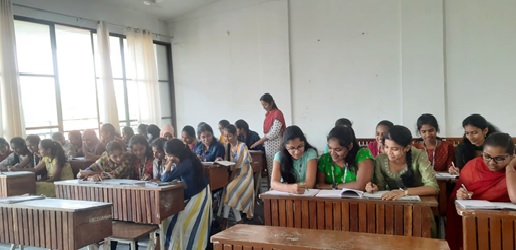
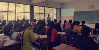
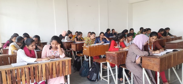
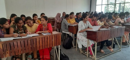
Activities used in teaching and learning
Activity 1
Faculty:
Ms. Y. Sharvani
Subject:
Microprocessors and Microcontrollers
Section:
III EEE
Topic Name:
Basics of microprocessor
Activity Name:
Think – Pair Share
Description of the Activity:
This activity is planned in the classroom for a duration of 10 minutes
- The teacher will pose few questions
- Individual thinking
- Forming pairs within themselves by choosing a partner of their own
- Think and discusses solution within their group
- If they disagree, each clarifies their position and determines how / why they disagree
- Keep the students engaged actively in the class room
Outcome:
The students think individually and discusses with their peers and solved the question and presented on the dais.
Activity 2
Faculty:
Mrs. Chinthireddy Padmaja
Subject:
Electronic Circuit Analysis
Section:
III ECE
Topic Name:
Power Amplifiers
Activity Name:
Collaborative Learning –STAD (Student Teams - Achievement Divisions)
| S.No | Topic Name | Description of activity | Outcome |
|---|---|---|---|
| 1 | Power Amplifiers |
|
There was an emphasis to learn and explain at the same moment. So students were able to understand the concepts without wasting their time. Slow learners learned from others within the team. It acted as a platform to improve their performance by discussing among themselves. It also helped in bridging the gap between lecturer and students. |
Activity 3
Faculty:
Mr. N. Govardhan
Subject:
VLSI System Design
Section:
III ECE
Topic Name:
CMOS Color Coding
Activity Name:
STAD (Student Teams - Achievement Divisions)
Description of the Activity:
- Students are divided in to 10 teams formed. Each team size is 4 members.
-
Based on the score secured by the students in the pretest, teams were formed by following steps
Listed the student numbers based on their score.
Arranged the numbers in ascending order of their secured score.
Teams are numbered with 1 to 10 i.e., Team 1, Team 2 and so on.
The top scored 10 students are the first person in each team. The next scored 10 students are the second person in each team and so on.
This strategy is used to make each team is a mix of different marks scored students. Each team consists from top level scorer to least scorer.
Because of mixed scored students in each team. It makes each team performed equally.
Activity 4
Faculty:
Mr. E. Kumaraswamy
Subject:
Digital Image Processing
Section:
IV ECE
Topic Name:
Image enhancement techniques are used to solve real time problems
Activity Name:
STAD (Student Teams - Achievement Divisions)
Description of the Activity:
- Students are divided in to 15 teams. Each team consists of 4 members.
-
Based on the score secured by the students in the present, teams were formed by following steps
Listed the student numbers based on their score and arranged the numbers in ascending order of their secured score.
Teams are numbered with 1 to 15 i.e., Team 1, Team 2 and so on.
The top scored 15 students are the first person in each team. The next scored 15 students are the second person in each team and so on.
This strategy is used to make each team is a mix of different marks scored students. Each team consists from top level scorer to least scorer.
Because of mixed scored students in each team. It makes each team perform ed equally.
Activity 5
Faculty:
Mr. M. Ramu
Subject:
EMFW
Section:
II ECE-A
Topic Name:
Maxwell’s Equations with Examples
Activity Name:
STAD (Student Teams - Achievement Divisions)
Description of the Activity:
- Students are divided in to 10 teams formed. Each team size is 4 members.
-
Based on the score secured by the students in the pretest, teams were formed by following steps
Listed the student numbers based on their score.
Arranged the numbers in ascending order of their secured score.
Teams are numbered with 1 to 10 i.e., Team 1, Team 2 and so on.
The top scored 10 students are the first person in each team. The next scored 10 students are the second person in each team and so on.
This strategy is used to make each team is a mix of different marks scored students. Each team consists from top level scorer to least scorer.
Because of mixed scored students in each team. It makes each team performed equally.
Activity 6
Faculty:
Chinthireddy Padmaja
Subject:
Electroic Measurements and Instrumentation
Section:
III ECE-A
Topic Name:
Special Purpose Oscilloscopes
Activity Name:
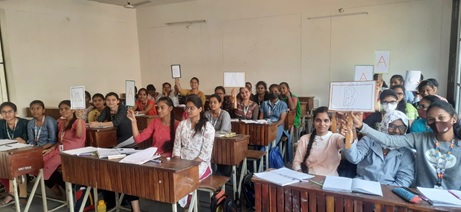
Concept tests
Description of the Activity:
This activity is planned for entire strength in the classroom
- A multiple-choice question is posed to the students (choices – 3 wrong answers and one correct answer).
- The students are to obtain the solution individually and note down the choice out of 4 options and then students were asked to show the cards indicating their choice.
- After looking at their answers, the students were suggested to form a group consisting of 3 members. Then students were asked to discuss and share their idea to get the answer with partners and reconcile the responses. Then the representative of each group was asked to show the card to indicate the choice of their group.
- Finally, lecturer discusses the problem and then gives the correct answer.
Outcome:
This activity created enthusiasm among students towards learning and pay attention in the classroom.
Activity 7
Faculty:
Chinthireddy Padmaja
Subject:
Electroic Measurements and Instrumentation
Section:
III ECE-B
Topic Name:
Special Purpose Oscilloscopes
Activity Name:
Think- Pair Share
Description of the Activity:
This activity is planned in the classroom for a duration of 10 minutes
- The teacher will ask few questions
- Individual thinking
- Forming pairs within themselves by choosing a partner of their own
- Think and discusses solution within their group
- If they disagree, each clarifies their position and determines how/why they disagree
- Keep the students engaged actively in the class room
Outcome:
The students think individually and discusses with their peers and solved the question and presented on the dais.
| S.No | Activity Conducted | Name of the Faculty | Course | Academic Year |
|---|---|---|---|---|
| 1 | Collaborative Learning | Dr. M. Gopal | Signals and Systems | 2021-22 |
| 2 | Concept Tests | Dr. M. Gopal | Signals and Systems | 2021-22 |
| 3 | STAD | Mrs. Chinthireddy Padmaja | Electronic Measurements and Instrumentation | 2021-22 |
| 4 | Think – Pair Share | Ms. Y. Sharvani | Analog and Digital Electronics | 2021-22 |
| 5 | Think – Pair Share | Mr. N. Govardhan | Digital System Design | 2021-22 |
| 6 | Think – Pair Share | Mrs. M. Anitha | Measuring Instruments | 2021-22 |
| 7 | Think – Pair Share | Mr. E. Kumaraswamy | Signals & Systems | 2021-22 |
| 8 | Harnessing the Power of Technology | Mr. D. Koteshwar Rao | Radar Systems | 2021-22 |
| 9 | Think – Pair Share | Mr. G. Mahesh Kumar | Mobile Communication and Networks | 2021-22 |
Activities used in teaching and learning
Activity 1
Faculty:
Dr. M.Gopal
Subject:
Signals and Systems
Section:
II ECE-B
Topic Name:
Fourier Transforms
Activity Name:
Collaborative Learning -STAD (Student Teams - Achievement Divisions)
| S.No | Topic Name | Description of activity | Outcome |
|---|---|---|---|
| 1 | Fourier Transform |
|
There was an emphasis to learn and explain at the same moment. So students were bound to understand the concepts without wasting their time. Slow learners learned from others within the team. It acted as a platform to improve their performance by discussing among themselves. It also helped in bridging the gap between lecturer and students. |
Activity 2
Faculty:
Dr. M Gopal
Subject:
Signals and Systems
Section:
II ECE-A
Topic Name:
Sampling
Activity Name:
Concept tests
Description of the activity:
This activity is planned for entire strength in the classroom
- A multiple choice question is posed to the students (choices – 3 wrong answers and one correct answer)
- The students are to obtain the solution individually and note down the choice out of 4 options and then students were asked to show the cards indicating their choice
- After looking at their answers, the students were suggested to form a group consisting of 3 members. Then students were asked to discuss and share their approach to get the answer with partners and reconcile the responses. Then the representative of each group was asked to show the card to indicate the choice of their group
- Finally, lecturer discusses the problem and then gives the correct answer
Outcome:
This activity created enthusiasm among students towards learning and pay attention in the classroom.
Activity 3
Faculty:
Mrs. Chinthireddy Padmaja
Subject:
Electronic Measurements and Instrumentation
Topic Name:
Performance Characteristics
Section:
III ECE
Activity Name:
STAD
STAD:
To implement this activity, teams were formed based on the academic score, teacher gives a set of questions, they have to discuss among themselves and have to share the answer finally they have to pick up the answer which is accepted by all, then the solution will be discussed in the class room.
Implementation Strategy:
15 teams were formed out of 60 students, and the task was assigned to each team and they discussed among themselves and solved the problem. This activity is planned for 40 minutes.
Challenges anticipated:
Maintaining discipline, while the activity was being performed.
Addressing the challenges during the class
The problem was solved by taking the help of other faculty while conducting the activity.
Outcome:
This activity was helped in improving students' listening and understanding levels. It gave students time to think about an answer and improved prior knowledge. This activity increased students' oral communication skills as they discussed their ideas with one another. It also helped the students to become active participants in learning.
Activity 4
Faculty:
Ms. Y. Sharvani
Subject:
Analog and Digital Electronics
Section:
II CSE
Topic Name:
Karnaugh Maps
Activity Name:
Think – Pair Share
Description of the Activity:
This activity is planned for the total students in the classroom.
- The teacher will pose a question
- Individual thinking
- Formed the pairs with students of their choice
- Think and discusses solution within their group
- If they disagree, each clarifies their position and determines how / why they disagree
Outcome:
The students were actively engaged in the classroom. They came to know each other and it also helped the students to become active participants in learning and generated various solutions for the questions from the discussions.
Activity 5
Faculty:
Mr. N. Govardhan
Subject:
Digital System Design
Section:
II ECE-A
Topic Name:
K-Map
Activity Name:
Think Pair Share
Description of the Activity:
This activity is planned in the classroom for a duration of 10 minutes.
- The teacher will pose few questions
- Individual thinking
- Forming pairs within themselves by choosing a partner of their own
- Think and discusses solution within their group
- If they disagree, each clarifies their position and determines how/why they disagree
- Keep the students engaged actively in the class room
Outcome:
The students started brainstorm about the given topic and solved the question and presented on the dais.
Activity 6
Faculty:
Mrs. M.Anitha
Subject:
Measuring Instruments
Section:
IV EEE
Topic Name:
Methods of Measurements
Activity Name:
Think- Pair Share
Description of the Activity:
This activity is planned in the classroom for a duration of 10 minutes.
- The teacher will pose few questions
- Individual thinking
- Forming pairs within themselves by choosing a partner of their own
- Think and discusses solution within their group
- If they disagree, each clarifies their position and determines how/why they disagree
- Keep the students engaged actively in the class room
Outcome:
The student thinks individually and discusses with their peers and solved the question and presented on the dais.
Activity 7
Faculty:
Mr. E. Kumaraswamy
Subject:
Signals & Systems
Section:
III EEE
Topic Name:
Basics of Signals and systems
Activity Name:
Think- Pair Share
Description of the Activity:
This activity is planned in the classroom for a duration of 10 minutes.
- The teacher will pose few questions
- Individual thinking
- Forming pairs within themselves by choosing a partner of their own
- Think and discusses solution within their group
- If they disagree, each clarifies their position and determines how/why they disagree
- Keep the students engaged actively in the class room
Outcome:
The student thinks individually and discusses with their peers and solved the question and presented on the dais.
Activity 8
Faculty:
Mr. D. Koteshwar Rao
Activity:
Harnessing the Power of Technology
Subject:
Radar Systems
Topic:
Conical Scan
OBJECTIVE:
Learning objective of this topic is to understand the conical scan topic practically. Watching these video students able to know how practically radar scans.
PLAN:
In my action plan first I selected the topic which is useful to the student with the harnessing the power of technology.
After selection of the topic (2nd step), gathered all the relevant information about the topic and prerequisites of the topic.
In third step I decided whether are there any readily available PPT (Power Pont Presentation) OR to prepare a new which will take 10mins maximum time.
In fourth step I choose and downloaded the screen recording software for that I used the BANDICAM software which is help to me for basic level presentation because I used a trail version it is record the video only 10mins, and also checked and practiced whether the topic complete or not within the time.
Finally I decided to share the YouTube video link through whatsapp.
For the preparation of PPT I browsed the web any animation videos are available but I did not find any animated video so a normal PPT was prepared.
WEBSITE LINK:
REFLECTIVE REPORT:
Using Harnessing technology was a good experience to me, I posted my you tube video link through whatsapp.
For recording the video I used the laptop, headset for clear audio recording along with BANDICAM SOFTWARE.
When I start recoding the video I had very much doubt about how will the students’ accepts it and how much they understand. After sharing the video, 90% (out of 60 students 55 have watched it within a day) and almost all of the students understood the topic very clearly. I checked whether they understood or not, by posing simple questions for which almost of them answered that’s why I’m very much satisfied.
For time management sake in middle of video i.e, from 5th to 6th minute fast explanation was done otherwise everything went well. So for the next time I maintain a constant teaching flow throughout the video.
I used trial version software so the video records only 10mins, next time for longer duration video I will change the software and also do my own animation ppt.
Activity 9
Faculty:
Mr. G. Mahesh Kumar
Subject:
Mobile Communication and Networks
Section:
III ECE
Topic Name:
Basic Cellular System
Activity Name:
Think- Pair Share
Description of the Activity:
This activity is planned in the classroom for a duration of 10 minutes.
- The teacher will pose few questions
- Individual thinking
- Forming pairs within themselves by choosing a partner of their own
- Think and discusses solution within their group
- If they disagree, each clarifies their position and determines how/why they disagree
- Keep the students engaged actively in the class room
Outcome:
The students think individually and discussed with their peers and solved the question and presented on the dais.
| S.No | Activity Conducted | Name of the Faculty | Course | Academic Year |
|---|---|---|---|---|
| 1 | Collaborative Learning | Mrs. Chinthireddy Padmaja | Electronic Measurements and Instrumentation | 2020-21 |
| 2 | Think-pair share | Mr. E. Kumaraswamy | Digital Image Processing | 2020-21 |
| 3 | STAD | Mrs. D. Raghava Kumari | Electronic Measurements and Instrumentation | 2020-21 |
| 4 | Harnessing the power of technology | Mr. K. Srinivas | LDICA | 2020-21 |
| 5 | Collaborative Learning | Mr. K. Srinivas | LDICA | 2020-21 |
| 6 | Harnessing the power of technology | Mr. K. Ravikiran | Microprocessors and Microcontrollers | 2020-21 |
Activities used in teaching and learning
Activity 1
Faculty:
Mrs. Chinthireddy Padmaja
Subject:
Electronic Measurements and Instrumentation
Section:
IV ECE
Topic Name:
Bridges
Activity Name:
Collaborative Learning –STAD (Student Teams - Achievement Divisions)
| S.No | Topic Name | Description of activity | Outcome |
|---|---|---|---|
| 1 | Bridges |
|
There was a scope to discuss among themselves and understand the concepts without wasting their time. Slow learners learned from others within the team. It provided a platform to improve their performance. It also helped in bridging the gap between lecturer and students. |
Activity 2
Faculty:
Mr. E. Kumaraswamy
Subject:
Digital Image Processing
Section:
IV ECE
Topic Name:
Spatial domain methods – Image Enhancement
Activity Name:
Collaborative Learning –STAD (Student Teams - Achievement Divisions)
| S.No | Topic Name | Description of activity | Outcome |
|---|---|---|---|
| 1 | Image Enhancement |
|
There was an emphasis to learn and explain at the same moment. So students were bound to understand the concepts without wasting their time. Slow learners learned from others within the team. It acted as a platform to improve their performance by discussing among themselves. It also helped in bridging the gap between lecturer and students. |
Activity 3
Faculty:
D.Raghava kumari
Subject:
EMI
Section:
III ECE
Topic Name:
Measurments
Activity Name:
STAD (Student Teams - Achievement Divisions)
Description of the Activity:
- Students are divided in to 15 teams formed. Each team size is 3 members.
-
Based on the score secured by the students in the pretest, teams were formed by following steps
Listed the student numbers based on their score.
Arranged the numbers in ascending order of their secured score.
Teams are numbered with 1 to 15 i.e., Team 1, Team 2 and so on.
The top scored 15 students are the first person in each team. The next scored 15 students are the second person in each team and so on.
This strategy is used to make each team is a mix of different marks scored students. Each team consists from top level scorer to least scorer.
Because of mixed scored students in each team. It makes each team performed equally.
Activity 4
Faculty:
Mr. K. srinivas
Activity:
Harnessing the Power of Technology
Subject:
Linear and Digital IC Application
Topic:
Flash ADC
OBJECTIVE:
Learning objective of this topic is to understand the one type of analog to digital converter.
Objective of recording this video is, it takes more time to draw the diagram of the flash type ADC and to explain the same it takes around 2 classes to finish the topic. By recording this video it takes around 8-10 minute to finish the topic.
PLAN:
In my action plan first I selected the topic which is useful to the student with the harnessing the power of technology.
After selection of the topic (2nd step), gathered all the relevant information about the topic and prerequisites of the topic.
In third step I decided whether are there any readily available PPT (Power Pont Presentation) OR to prepare a new which will take 10mins maximum time.
In fourth step I choose and downloaded the screen recording software for that I used the BANDICAM software which is help to me for basic level presentation because I used a trail version it is record the video only 10mins, and also checked and practiced whether the topic complete or not within the time.
Finally I decided to share the YouTube video link through whatsapp.
For the preparation of PPT I browsed the web any animation videos are available but I did not find any animated video so a normal PPT was prepared.
WEBSITE LINK:
REFLECTIVE REPORT:
Using Harnessing technology was a good experience to me, I posted my you tube video link through whatsapp.
For recording the video I used the laptop, headset for clear audio recording along with BANDICAM SOFTWARE.
When I start recoding the video I had very much doubt about how will the students’ accepts it and how much they understand. After sharing the video, 90% (out of 60 students 55 have watched it within a day) and almost all of the students understood the topic very clearly. I checked whether they understood or not, by posing simple questions for which almost of them answered that’s why I’m very much satisfied.
For time management sake in middle of video i.e, from 5th to 6th minute fast explanation was done otherwise everything went well. So for the next time I maintain a constant teaching flow throughout the video.
I used trial version software so the video records only 10mins, next time for longer duration video I will change the software and also do my own animation ppt.
Activity 5
Faculty:
Mr. K. srinivas
Activity:
Collaborative learning
- Collaborative learning activity:
- Course, Topic & how collaborative activity will help:
- Give the students a taste of the applications of the theories taught in the subject. This will be achieved through the project, collaborative learning activity and some selected lab sessions.
- Give the students a useful skill base that would allow them to carry out further study should they be interested and to work in the field.
- Objective of the Activity
- Plan to Create Teams
- Based on their pretest performance, I group the teams and ensure that, each team should consist of low to high basic knowledge capable students.
- The size of the team would be 4 members.
- Total strength in my class is 42 students. Hence, I need to handle 11 teams.
- Time and plan of activity
-
In 1st week 1st hour:
Conduct the pre-test and form groups and encourage the students and give the instructions of the activity.
-
In 1st week 2nd hour:
I will be explain the clock signal generators using IC555 timers.
-
In 1st week 3rd hour:
I will be explain the difference of clock signal generators or multivibrator using IC555 timers and OP-AMP.
-
In 1st week 4th hour:
In each group one student give his presentation 5min, what they learn in this week.
-
In 2nd week 1st hour:
I will be explain the applications of the each signal generator.
-
In 2nd week 2nd hour:
I theoretical explain designing process of signal generators.
-
In 2nd week 3rd hour:
Gives the designing problem to the each groups.
-
In 2nd week 4th hour:
In each group one student give his presentation 5min about what are the results with them and justification of it.
-
In 3rd week starting three hour:
In these three students are supposed to practically verify their designed value either simulation lab / analog electrical lab and also observe the theoretical and practical variations.
-
In 3rd week 4th hour:
In each group one student give his presentation 5min about what they observed theoretical and practical values are matched or not.
- Evaluate the Group and Individual performance
STAD (Student Team Achievement Divisions)
Course is LINEAR AND DIGITAL IC APPLICATIONS
Topic is designing problem of signal generator for pulse carrier modulation.
The object of this topic is: To utilize the designing process and applied it in real time application like pulse carrier modulation in digital and analog communication.
This activity will Develops higher level thinking skills and Student can build self-esteem and promotes a positive attitude toward the subject learning. Students able to explore alternate problem solutions in a safe environment and Stimulates critical thinking and helps students clarify ideas through discussion and debate.
At the end of the activity, the students will able to
Design the clock generator real time application
Learn the real time application of the clock signal generators
I conduct a pre-test to the students to know about individual abilities. It will be considered while calculating the overall score of a student.
Strategy for Team Formation:
Before start the activity, I give a lesson on basics about signal generators with some simple examples.
In different applications they applied the knowledge & topic what they learn.
The total duration of the activity is about 3 weeks, each week 4 hours.
I will give square signal / clock signal real time application problems.
These three weeks activity is summarized as
First, student need to go through the various IC’s are used to generate square signals.
Let them to learn the operation of each and every circuit, analysis which provide required voltage and response voltage and current values.
Apply the techniques to understand the given problem within group by oral discussions or lab session.
To perform this, they need lab so I will provide a session in the analog electronics lab.
Student need to solve the assigned problem individually.
I plan to conduct a 5 minute presentation of each student in every week, to know about their progress and type of difficulties they faced.
I also facilitate and motivate to complete the task.
Assessment of individual performance is going to be done. Using the rubric given below in every week.
Each student’s incremental score is calculated based on his pre-test score.
The team member’s individual scores are then added to calculate the team score
I keep monitoring the progress of each team and individuals performance in team.
If a particular team is deviated from the task, then I instructed to make it in right way.
Upon successfully completing the activity, the student should be able to have an appreciation of the fundamentals of signal generators including the topics of analysis and design. Be able to implement carrier signal generators in communication where modulation and demodulation techniques are used.
| Evaluation rubric for team performance | ||||
|---|---|---|---|---|
| Criteria | Ratings | Pts | ||
| As they choose correct solution | 3.0 pts Perfect option |
2.0 pts Fairly Good |
1 pts Poor – NOT matched |
3 pts |
| As they applied the theoretical concept | 4.0 pts Very Good-collective and applied |
2.0 pts Fairly Good –only collective or applied |
0.0 pts Poor - NOT used |
4.0 pts |
| Practical and theoretical analysis matched | 3.0 pts Perfectly matched and justified |
2.0 pts Matched but justification is missed 1.0 pts not matched but justified |
0.0 pts NOT matched |
3.0 pts |
| Total | 10 pts | |||
Evaluate the team member’s individual performance
| Evaluation rubric for team member’s individual performance | ||||
|---|---|---|---|---|
| Criteria | Ratings | Pts | ||
| Active participation of student in the team | 2.0 pts Very Good |
1.0 pts Fairly Good |
0.0 pts Poor - NOT participated, Need motivation to make him / her active |
2.0 pts |
| The student is collective and integrate the information with available resources | 2.0 pts Very Good-collective and integrate |
1.0 pts Fairly Good – only collective or integrate |
0.0 pts Poor - NOT participated |
2.0 pts |
| Analyze and apply in the lab to meet the required goals | 3.0 pts Very Good - Perfect way of doing the task and they did it |
2.0 pts Fairly Good - facing some difficulties and motivation needed |
1.0 pts Poor – Not tried confusing. Work hard to involvement and motivation |
3.0 pts |
| The activity completed in time and followed instructions strictly | 3.0 pts Very Good - They did it in time |
2.0 pts Fairly Good- they did in time but did not properly follow the instructions |
1.0 pts Poor – they did not complete in time |
3.0 pts |
| Total | 10 pts | |||
Evaluate the team performance
| Individual performance (Xi) |
X (Max) | Y(Max=10) | Team performance (Max=10) |
|
|---|---|---|---|---|
| Student 1 | X1 | x = (X1 + X2 + X3 +X4) / 4 | From Evaluation rubric for team performance | Team performance = (X + Y) / 2 |
| Student 2 | X2 | |||
| Student 3 | X3 | |||
| Student 4 | X4 |
Activity 6
Faculty:
Mr. K. Ravi Kiran
Activity:
Harnessing the Power of Technology
Course:
Microprocessors and Microcontrollers
Learning unit:
Interfacing peripherals to 8051 microcontroller
Topic:
Interfacing seven segment display to 8051 microcontroller
Simulation / Virtual lab:
8051 Microcontroller and Applications
Justification:
I choose this specific experiment to be conducted in the virtual lab because this will make students to visually watch the debugging in a step by step manner and also in burst mode of execution.
This virtual lab environment also makes the students observe and understand how to interface a seven-segment display to 8086, which they can’t observe in the physical laboratory available in the college.
This also makes students how to connect a crystal oscillator, resistor, and capacitor to a controller which will be helpful to the students while carrying out the academic projects in embedded systems using 8051 microcontroller.
By performing this experiment students can clearly understand the port requirements to connect a seven-segment display to a microcontroller and also verify the logic levels on the port visually which creates a greater impact in understanding the experiment.
-
Link to the virtual lab:
http://vlabs.iitb.ac.in/vlabs-dev/labs/8051-Microcontroller-Lab/labs/exp1/index.php - Manual
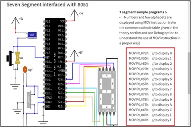
- A brief introduction to Interfacing seven segment display to 8051
- Common cathode display
- Common anode display
- Instructions for performing the simulation
-
Go to the following link
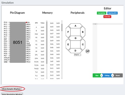
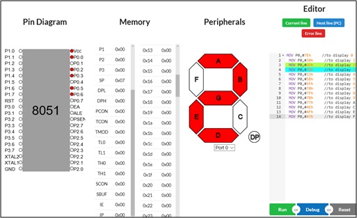
http://vlabs.iitb.ac.in/vlabs-dev/labs/8051-Microcontroller-Lab/labs/exp1/index.php - Click on the simulation which is available to the left side of the page, then a pop up with name important note saying this lab doesn’t support timer and serial are not supported will be opened, click OK as this program doesn’t require timers.
- Once OK is clicked the following type of window will be opened, then click on the show Sample: Displays which is available beneath the 8051 controller pin diagram.
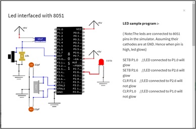
- Then a pop-up window will be opened showing Led interfaced with 8051, scroll down in the window till you see Seven Segment interfaced with 8051 which shows the interfacing diagram and code. (*Note: Common cathode display is used in this experiment)
- Copy the seven-segment sample program(port 0 is employed), close the pop-up window, and paste the code in the Editor tab available towards the right side as shown in figure 5.
- vi. Then debug the program, where we can see step by step execution, where the number is displayed on the seven-segment display, and its respective logic levels on the pin diagram (red indicates logic 1).
- We can write our desired program in the editor tab to display all the possible characters that are supported by the seven-segment display.
- Quiz
-
To display the letter “d” by using common anode seven segment display,
what are logic levels that are to be transmitted from microcontroller to display?
- a=1, b=0, c=0, d=0, e=0, f=0, g=1
- a=0, b=1, c=1, d=1, e=1, f=0, g=1
- a=1, b=0, c=0, d=0, e=0, f=1, g=0
- a=1, b=0, c=0, d=1, e=0, f=0, g=1
-
While debugging the program for displaying the digit “5”
which of the following port pins of the port 0 are it logic high level.
- P0.0, P0.1, P0.3, P0.5, P0.6
- P0.0, P0.1, P0.3, P0.4, P0.6
- P0.0, P0.1, P0.3, P0.5, P0.6
- P0.0, P0.1, P0.3, P0.5, P0.6
-
In common cathode seven segment display, MOV P0, #37h displays which character / digit.
- B
- D
- F
- H
-
Which additional component is placed between 7 segment display and
microcontroller in order to display numbers greater than 9?
- Decoder
- Multiplexer
- Demultiplexer
- Encoder
-
Who is known as the father of light emitting diode?
- James R. Biard
- Gary Pittman
- Nick Holonyak
- None
8051 microcontroller
8051 is an 8 bit CISC (complex instruction set computer) based microcontroller fabricated with N-MOS technology, available in the DIP (Dual-in-line pin) package. It operates at a frequency of 11.0592 MHz and provides 4 ports (port 0, port 1, port2, and port3) which are used to connect peripherals without additional hardware. It also consists of 128 bytes of RAM and 4 KB of ROM. These are some of the features of 8051 that are to be known to perform to this experiment.
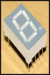
Seven segment display
As per the name, a seven-segment display comprises of seven LEDs (Light emitting diode) arranged as per figure 1. This display will display all numbers from 0 to 9 and also is capable of displaying some of the alphabetical letters as shown in figure 2.
There is an additional 8th LED (a dot) which is represented as DP (decimal point) which is used when more than one seven-segment displays are connected to display numbers greater than 9.

As each LED has two terminals namely anode and cathode, there are two types of displays available namely
Common cathode display
In this display, all the cathodes of the display are joined together and connected to logic 0. To illuminate any of the segments of the display, logic 1 through a current limiting resistor has to be applied for the sake of forward biasing the individual Anode terminals.
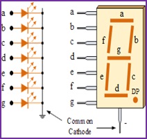
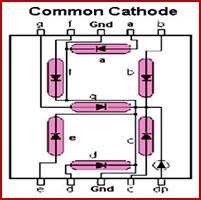
Figure 3: Common cathode display a. in general form b. in IC form
The following truth table gives a clear picture regarding the hexadecimal codes for illuminating individual segment to display a specific character
| Decimal digit / Character | Individual segment illuminated | Hexadecimal equivalent of Individual segment illuminated | ||||||
|---|---|---|---|---|---|---|---|---|
| a | b | c | d | e | f | g | ||
| 0 | 1 | 1 | 1 | 1 | 1 | 1 | 0 | 7E |
| 1 | 0 | 1 | 1 | 0 | 0 | 0 | 0 | 30 |
| 2 | 1 | 1 | 0 | 1 | 1 | 0 | 1 | 6D |
| 3 | 1 | 1 | 1 | 1 | 0 | 0 | 1 | 79 |
| 4 | 0 | 1 | 1 | 0 | 0 | 1 | 1 | 33 |
| 5 | 1 | 0 | 1 | 1 | 0 | 1 | 1 | 5B |
| 6 | 1 | 0 | 1 | 1 | 1 | 1 | 1 | 5F |
| 7 | 1 | 1 | 1 | 0 | 0 | 0 | 0 | 70 |
| 8 | 1 | 1 | 1 | 1 | 1 | 1 | 1 | 7F |
| 9 | 1 | 1 | 1 | 1 | 0 | 1 | 1 | 7B |
| A | 1 | 1 | 1 | 0 | 1 | 1 | 1 | 77 |
| C | 1 | 0 | 0 | 1 | 1 | 1 | 0 | 4E |
| E | 1 | 0 | 0 | 1 | 1 | 1 | 1 | 4F |
| F | 1 | 0 | 0 | 0 | 1 | 1 | 1 | 47 |
Table 1: Truth table of common cathode 7 segment display or digit dive pattern
Common anode display
In this display, all the anodes of the display are joined together and connected to logic 1. To illuminate any of the segments of the display, logic 0 through a current limiting resistor has to be applied to the cathode terminal of the required segment.
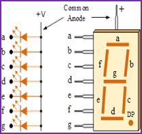
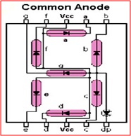
Figure 4: Common anode display a. in general form b. in IC form
The following truth table gives a clear picture regarding the hexadecimal codes for illuminating individual segment to display a specific character
| Decimal digit / Character | Individual segment illuminated | Hexadecimal equivalent of Individual segment illuminated | ||||||
|---|---|---|---|---|---|---|---|---|
| a | b | c | d | e | f | g | ||
| 0 | 0 | 0 | 0 | 0 | 0 | 0 | 1 | 01 |
| 1 | 1 | 0 | 0 | 1 | 1 | 1 | 1 | 4F |
| 2 | 0 | 0 | 1 | 0 | 0 | 1 | 0 | 12 |
| 3 | 0 | 0 | 0 | 0 | 1 | 1 | 0 | 06 |
| 4 | 1 | 0 | 0 | 1 | 1 | 0 | 0 | 4C |
| 5 | 0 | 1 | 0 | 0 | 1 | 0 | 0 | 24 |
| 6 | 0 | 1 | 0 | 0 | 0 | 0 | 0 | 20 |
| 7 | 0 | 0 | 0 | 1 | 1 | 1 | 1 | 0F |
| 8 | 0 | 0 | 0 | 0 | 0 | 0 | 0 | 00 |
| 9 | 0 | 0 | 0 | 0 | 1 | 0 | 0 | 04 |
| A | 0 | 0 | 0 | 1 | 0 | 0 | 0 | 08 |
| C | 0 | 1 | 1 | 0 | 0 | 0 | 1 | 31 |
| E | 0 | 1 | 1 | 0 | 0 | 0 | 0 | 30 |
| F | 0 | 1 | 1 | 1 | 0 | 0 | 0 | 38 |
Table 2: Truth table of common anode 7 segment display or digit dive pattern
Interfacing 7 segment display to 8051
To interface a seven-segment display that is available in the form of a 10 pin DIP package, any one of the 8-bit port of microcontroller has to be used. Out of 10 pins available in the display IC (integrated chip), 7 pins are for illuminating individual segments of the display, one is DP (decimal point) and the remaining two pins are common pins. These common pins are to be connected to ground in common cathode configuration whereas to be connected to Vcc (+5 volts) in common anode configuration.
Port 0 is employed to connect the display to the microcontroller in the sample program given in the virtual lab environment. But any of the four ports can be used, which can be verified by you.
Additional instruction:
Go through the pre-test to test the basics and post-test to test the knowledge what you have learned by experimenting

UGC AUTONOMOUS
 Accredited by
NAAC
 Affiliated to
JNTUH
 Approved by
AICTE
 Accredited by
NBA
ADDRESS
Ananthasagar, Hasanparthy, Warangal, Telangana, India - 506371.